Aivia Software
Object Settings
Object Settings is one (1) of the four (4) display settings sections. This section lets you adjust the appearance of each object set, as well as any additional overlay options, on the currently displayed image. The adjustments applied here only change how the image is shown in the Image Viewer and do not change the underlying data on the image.
Interface
The object settings display can be broken up into 3 sections, the Toolbar area, the Object Set Trees area, and the Display Settings area.

On this page:
Toolbar
The toolbar contains high level actions.
| Name | Icon | Description |
|---|---|---|
| Collapse All |
| Collapses all object sets in the tree view. |
| Expand All |
| Expands all object sets in the tree view. |
| Create Object Set Templates |
| Creates empty object set trees. Opens a menu from which you can select to create an empty outline, mesh, or neuron set. You may choose to add objects created with the Outline Editor or 3D Tools to these sets, for example. |
| Copy Selected Objects |
| If any objects selected, copies selected objects into a new object set structure like the existing one, an existing object set structure that's similar (e.g. neurons into neurons), or any mesh based objects into a standalone mesh object set. |


Object Set Tree View
The Object Set Tree View shows all object hierarchies, if any, on the image. The hierarchy of object sets represents different types of objects found on the image, such as Neurons, and all their components, like Somas, Dendrites, and Spines. It also contains any subsets associated with those object sets.
Object Set: 
Object Subset: 
You can control the visibility of any individual object set with the  button. The top level object set will toggle the visibility of all the object sets below it, as well as copy any display settings to all child object sets.
You can see the count for the set (n=Count) as well as the percentage of the parent object set. Note that the percentage pertains to the object set that that the subset is under and is not the percentage of the parent object subset (e.g. the percentage of the Affected subset on the right is based on the number of objects in Dendrite Set, and not the number of objects in the Treatment subset)
You can select an object set in this view, and more detailed settings will appear in the Detailed Display Settings area.

Display Settings
In the display settings, you can see all the display settings for the object set or subset currently selected in the Object Set Tree View. Depending on what's selected, and what type of objects it contains, you may see different settings.


Buttons
Each table row in the Display Settings panel represents a single aspect of the currently selected object set or object subset. Each row can be controlled independently to adjust the display settings. There are six (6) basic controls for nearly every object set:
| Name | Icon | Description |
|---|---|---|
| Toggle Visibility |
| Shows or hides the object set from view |
| Load Recipe Settings |
| Loads the recipe settings and parameters used to generate this object set into the Recipe Console. It's grayed out if the object set was not made using the recipe console. Only available on the top object set in an object set hierarchy. |
| Export Objects to a Mask |
| Exports the objects to a mask or channel; You may export to the following:
|
| Select Object Color Scheme |
| Specifies the coloring mode for the object set |
| Select Object Transparency |
| Specifies the percent transparency of the object set. |
| Select Rendering Mode |
| Specifies the rendering mode of the object set in 3D View; the available options are the following:
|


Additional controls that are specific to particular object types are summarized in the table below.
| Object Type | Name | Icon | Description |
|---|---|---|---|
| Dendrites | Select Dendrite Display Mode |
| Specifies the display style for dendrite display, there are three (3) options:
|
| Tracks, Spots | Set Overlay Radius |
| Specifies the radius of the overlay display; this can be applied to tracks, anchors, trends, and spots |
| Tracks | Set Track Length |
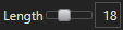
| Specifies the number of frames to display with the track overlay; a longer track length may result in reduced performance |
| Show/Hide Track Labels |
| Shows/Hides track labels in Main View (2D) | |
| Select Anchor Display Mode |
| Specifies the display style of the anchor overlay; there are two (2) options:
| |
| Set Trend Display Mode |
| Specifies the display style of the trend overlay; there are three (3) options:
|


Using the Object Set Settings
The Object Set Settings panel is active whenever you have an image loaded in Aivia. The software automatically populates the table based on the object sets and object types that are in the image file, if there are any.
Display settings in the top level object set in a tree often affect the settings for each object set in its hierarchy. The names of object sets can be edited after their names are double-clicked in the Display Settings header or in the Object Set Tree View.
Set display visibility
Each object set can be shown or hidden separately with the Toggle Visibility icon to the left of its name. The icon has two states:
| Display State | Icon | Description |
|---|---|---|
| Shown |
| The associated item is visible; click on the icon to hide the associated item |
| Hidden |
| The associated item is not visible; click on the icon to show the associated item |

For object trees, you can show or hide every object set in the group with the Toggle Visibility icon on top level object set.
Additionally, the right click menu has several options for quickly set the visibility of multiple object sets.

- Show all object sets will set the visibility of all object sets to visible.
- Hide all object sets will set the visibility of all objects sets to hidden.
- Show only "<Clicked Set>" will hide every set except the clicked on set.
- Show only "<Clicked Set>" and its tree will set every child in the tree to visible and every other to hidden.
- Show "<Clicked Set>and its tree will set all child sets in the tree to visible.
- Hide "<Clicked Set> and its tree will set all child sets in the tree to hidden.
Specify object display options that are unique to object types
The options available for displaying object sets and overlays depend on the object types. Please refer to the following pages for more information:
Change object set color
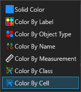
You can change the object set color display by clicking on the icon (or colored rectangle) associated with the object set in the Color column. Clicking on the icon will bring up a color picker menu which allows you to specify a different color or different coloring mode. There are seven (5) coloring options:
- Solid color applies the same color to every object in the group
- Color by object type applies the same color to the same type of object (e.g. meshes, dendrites, spines)
- Color by name applies a different color to each object depending on the name of the object
- Color by measurements applies a different color to each object depending on its value for a specified measurement
- Color by cell is specific to neuron and whole-cell objects and applies a different color for each neuron or whole cell
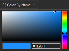
When you click on the icon in the Color column, the coloring option selector appears (see right). To change the coloring type, click on the dropdown menu in the selector.
You can also apply a specific color using the color picker below the dropdown menu. Click or drag the slider on the right to specify the desired hue (color) and click anywhere on the main display to specify the saturation and brightness desired. Alternately, you can specify a color by entering the hexadecimal color code in the textbox below the main display.
|
| Object color options |
|
| Coloring option selector |
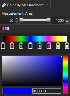
Color objects by measurements
When you select the Color By Measurement option, a different coloring selector appears. You can specify the measurement you want to use as well as the color palette and measurement range. The Color By Measurement selector is shown on the right.
Click on Measurement to open a dropdown menu listing all the available measurements that can be used for this coloring mode. Click on a measurement name to select the measurement.
The minimum and maximum values are shown in the slider below the measurement selector. The values are automatically populated based on the minimum and maximum object measurements on the image. You can drag the slider to define the desired value range to color.
Below the value slider is the color palette selector, where you can specify a color gradient for coloring the measurements. Additionally, you can adjust the gradient by dragging each of the color markers or change the color using the color picker below.
|
| Color By Measurement selector |
Coloring by Object Subsets

In addition to the coloring options presented above there are some options for coloring a single object set to display which objects are part of which subset. These options can be found by right clicking an object set or object subset in the Object Set Tree View. Subsets being used for display will have the  icon next to them in the tree view. Emphasized sets/subsets will have their names bolded.
- Spotlight affects the clicked on object set or object subset. It colors all objects that are in direct child subsets by their subset color, and any object not in a child subset gets colored by the parent object set/subset. If an object falls into more than one child subset, it will be colored white in 2D, and gray in 3D. In addition, all objects in the parent set well be emphasized.
- Emphasize makes it so that objects that are emphasized stand out from non-emphasized objects. This is done by making non-emphasized objects much lighter and more transparent than emphasized objects. This currently only works on 2D object types.
- Display using object set/subset color will override the display of any objects in that set to use the display color/mode of the set/subset you've selected. This provides a more granular display control over something like spotlighting.
- Clear emphasis will remove the emphasis state on all objects in the field.
- Clear display set will revert any spotlighting, emphasis, and revert to coloring objects just by their parent object set.
