- Created by Hoyin Lai , last modified by Aiden Maloney-Bertelli (Unlicensed) on Feb 08, 2021
You are viewing an old version of this content. View the current version.
Compare with Current View Version History
« Previous Version 26 Next »
The Neuron Composer lets you create new or edit existing neuron objects (generated using the 3D Neuron Analysis recipes or Mesh Contour Editor) in 3D View manually. The Neuron Composer provides tools for editing dendrite segments, adding somas (cell bodies), and adding spines. When you complete an edit, the Neuron Composer automatically updates the neuron measurements as well as the display of the edited neurons.
Interface
The Neuron Composer is one (1) of eight (8) tools found in the 3D Tools tab of the Analysis Panel. Go to 3D View to show the 3D Tools tab. Click on the 3D Tools tab, and then click on the Neuron Composer icon to launch the tool. When you first launch the Neuron Composer, the display settings are updated to show neuron objects and color them by object label. To start editing, select a tool from the Edit Mode section at the top of the Neuron Composer GUI.
Neuron Composer interface with the Neuron Composer icon highlighted
Edit modes
The Edit Mode box contains the editing tools for the Neuron Composer. When you select a tool, you enter a specific edit mode that lets you modify certain parts of the neuron objects (i.e., somas, dendrites, or spines). Descriptions and functions for all editing tools in the Neuron Composer are summarized in the table below, and the options for each edit mode are explained in the subsections to follow.
| Edit mode | Icon | Hotkey | Description |
|---|---|---|---|
| Predict Dendrite |
| E | Toggles the Predict Dendrite mode for algorithm-assisted dendrite tracing |
| Draw Dendrite |
| D | Toggles the Draw Dendrite tool for WYSIWYG dendrite tracing in the 3D volume |
| Connect Neurons |
| C | Toggles the Connect Neurons tool for joining dendritic segments |
| Delete Dendrite Points |
| F | Toggles the Delete Dendrite Points tool that removes individual dendritic points |
| Add Spine |
| S | Toggles the Add Spine tool for one-click spine creation |
| Add Soma |
| A | Toggles the Add Soma tool for one-click soma creation |
| EM Create |
| M | Toggles the EM Create tool for point-by-point dendrite tracing |
| EM Update |
| Toggles the EM Update tool for updating the segmentation of dendrite meshes following edits to dendrite trees |
On this page:
Predict Dendrite interface
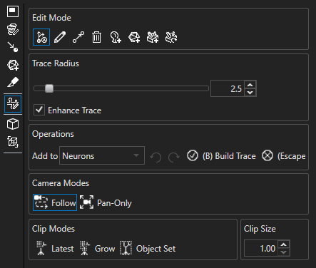
The Predict Dendrite tool offers algorithm-assisted dendrite tracing and has the interface shown on the right. The available options and parameters for Predict Dendrite are grouped into five (5) sections—Trace Radius, Operations, Camera Modes, Clip Modes, and Clip Size—and described in the table below.
| Section | Option | Description |
|---|---|---|
| Trace Radius | Trace Radius | Specifies the radius of the drawn dendrite trace and the maximum search distance between adjacent dendrite points; the radius parameter is relative to your computer display and not to the physical width of the dendrite in the image |
| Enhance Trace | Lets you override the specified dendrite radius of the drawn trace by estimating the approximate radius at each point using the intensity of the segment | |
| Operations | Add To | Specifies the object group to output the edited objects to |
| Undo | Undoes the last edit | |
| Redo | Redoes the last edit | |
| (B) Build Trace | Creates a dendrite from the trace in progress | |
| (Escape) Clear | Clears the trace in progress | |
| Camera Modes | Follow | Follows the predicted trace, moving the camera automatically to fit the trace |
| Pan-Only | Follows the predicted trace with panning only, keeping the same angle of view | |
| Clip Modes | Latest | Clips to the current prediction and last path segment added |
| Grow | Clips to the current prediction and all segments in the current trace | |
| Object Set | Clips to the current prediction and all objects in the output object set | |
| Clip Size | Clip Size | Specifies the size of the clipping box |
Predict Dendrite interface
Draw Dendrite interface
The Draw Dendrite tool allows you to draw dendrites on a 3D volume with more manual control than the Predict Dendrite tool provides. The interface for the Draw Dendrite tool is shown on the right, and the options and parameters available for the tool are described in the table below.
| Section | Option | Description |
|---|---|---|
| Trace Radius | Trace Radius | Specifies the radius of the drawn dendrite trace and the maximum search distance between adjacent dendrite points; the radius parameter is relative to your computer display and not to the physical width of the dendrite in the image |
| Enhance Trace | Lets you override the specified dendrite radius of the drawn trace by estimating the approximate radius at each point using the intensity of the segment | |
| Operations | Add To | Specifies the object group to output the edited objects to |
| Undo | Undoes the last edit | |
| Redo | Redoes the last edit |
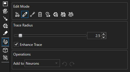
Draw Dendrite interface
Connect Neurons interface
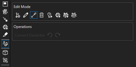
The Connect Neurons tool can be used to join dendritic segments to each other as well as to somas. The Connect Neurons interface is shown on the right, and descriptions of the available options are given in the table below.
| Section | Option | Description |
|---|---|---|
| Operations | Undo | Undoes the last edit |
| Redo | Redoes the last edit |
Connect Neurons interface
Delete Dendrite Points interface
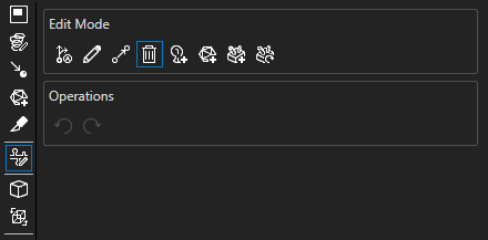
The Delete Dendrite Points tool can be used to delete individual dendrite points and has the interface shown on the right. Descriptions of the available options are given in the table below.
| Section | Option | Description |
|---|---|---|
| Operations | Undo | Undoes the last edit |
| Redo | Redoes the last edit |
Delete Dendrite Points interface
Add Spine interface
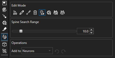
The Add Spine tool allows for one-click spine creation and has the interface shown on the right. The table below contains descriptions of the available options and parameters for the tool.
| Section | Option | Description |
|---|---|---|
| Spine Search Range | Spine Search Range | Specifies the maximum search distance (in voxels) for spines from the nearest dendrite segment |
| Operations | Add To | Specifies the object group to output the spine to |
| Undo | Undoes the last edit | |
| Redo | Redoes the last edit |
Add Spine interface
Add Soma interface
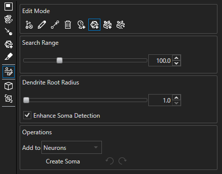
The Add Soma tool allows for one-click soma creation and has the interface shown on the right. The table below contains descriptions of the available options and parameters for the tool.
| Section | Option | Description |
|---|---|---|
| Search Range | Search Range | Specifies the maximum detection radius (in voxels) from the selected point for soma detection |
| Dendrite Root Radius | Dendrite Root Radius | Specifies the dendrite radius (in voxels) at the soma, which increases detection accuracy with enhanced soma detection |
| Enhance Soma Detection | Lets you use an advanced algorithm to produce a more accurate soma given the Dendrite Root Radius; with this off, a threshold is used, creating a soma that more closely matches the preview | |
| Operations | Add To | Specifies the object group to output the soma to |
| Create Soma | Creates a new soma object based on the selected location and specified parameters and options | |
| Undo | Undoes the last edit | |
| Redo | Redoes the last edit |
Add Soma interface
EM Create interface
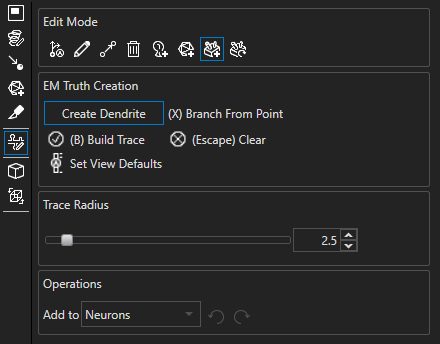
The EM Create tool allows you to create dendrite segments and branches point by point. The interface for the EM Create tool is shown on the right, and the available options and parameters for the tool are described in the table below.
| Section | Option | Description |
|---|---|---|
| EM Truth Creation | Create Dendrite | Allows you to place dendrite point when enabled |
| Branch From Point | Allows you to select a dendrite point to branch from | |
| (B) Build Trace | Creates a dendrite from the trace in progress | |
| (Escape) Clear | Clears the trace in progress | |
| Set View Defaults | Adjusts the display settings to those that are recommended for the EM Create tool | |
| Trace Radius | Trace Radius | Specifies the radius of the drawn dendrite trace; the radius parameter is relative to your computer display and not to the physical width of the dendrite in the image |
| Operations | Add To | Specifies the object group to output the dendrites to |
| Undo | Undoes the last edit | |
| Redo | Redoes the last edit |
EM Create interface
EM Update interface
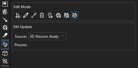
The EM Update tool allows you to update the segmentation of dendrite meshes based on the tree structure and has the interface shown on the right. The options for the EM Update tool are described in the table below.
| Section | Option | Description |
|---|---|---|
| EM Update | Source | Specifies the object group to update |
| Process | Segments the dendrite meshes based on the dendrite tree structure |
EM Update interface
Tool-specific hotkeys
| Hotkey | Edit Mode(s) | Action |
|---|---|---|
Shift + A | Add Soma | Confirm soma creation |
Ctrl + Left-Click | Predict Dendrite | Terminate a potential path by holding Ctrl and clicking on the path |
H | Predict Dendrite | Hide the current trace while the key is held |
B | Predict Dendrite EM Create | Create a dendrite from the trace in progress |
Esc | Predict Dendrite EM Create | Clear the trace in progress |
X | EM Create | Toggle on Branch From Point mode |
Using Neuron Composer
To launch the Neuron Composer tool, click on the 3D Tools tab in the Analysis Panel in Aivia and select the Neuron Composer tool from the 3D Tools toolbar. This will open the Neuron Composer interface.
Trace new dendrites
The Draw Dendrite tool lets you draw new dendrites directly on the 3D volume. Click on the Draw Dendrite tool icon or press the D key on your keyboard to enter this mode. The cursor display will change to a pencil with the tip of the pencil (lower-left corner) as the tracing position.
Before tracing a dendrite, make sure the channel displaying the dendrite is visible. Depending on the intensity of the dendrite and the density of objects in the volume, you may need to adjust the lookup table or add a clipping plane to isolate the desired dendrite. The Draw Dendrite tool uses ray tracing to find the closest opaque (i.e., non-background) signal directly in the line of sight of the displayed volume. To trace, hold down the left mouse button while dragging the mouse cursor along the dendrite.
Each point the Draw Dendrite tool finds along the dendrite is shown as a sphere in the volume. As you trace along the dendrite, additional spheres (dendrite points) are added to the trace. To finalize the trace, release the left mouse button; Aivia will connect the detected dendrite points to form a single dendritic segment and attempt to clean up the trace by removing any points that overlap the constructed trace.
The video on the right shows an example of using the Draw Dendrite tool to trace dendrites.
For even finer control over the placement of dendrite points, you may use the EM Create tool, which is designed for creating and editing dendrite traces for 3D electron microscopy images. It is recommended that this tool be used while stepping through the image slice-by-slice with an ortho plane. You may click on the Set View Defaults button in the EM Create interface to set the recommended display settings for this editing tool.
When Create Dendrite is enabled in the EM Create tool, left-click on the image to place a dendrite point. Once you have placed all dendrite points on the current trace that you would like to add, click on Build Dendrite or press B to finalize the dendrite segment. You can also branch off of existing dendrite segments in EM Create mode by first enabling Branch From Dendrite, then selecting the dendrite point to branch from (the selected point will turn yellow), placing dendrite points in the branch segment, and finally clicking on Build Dendrite or pressing B to finalize the branch.
Adjust dendrite radius
You can adjust the Trace Radius by moving the slider or entering a new value into the textbox. Increasing the Trace Radius results in thicker dendrite traces and increases the search radius for finding dendrite points. This option is useful for tracing dendrites with discontinuous signals. The radius parameter is relative to your computer display and not to the physical width of the dendrite in the image.
Enhance trace
The Enhance Trace option overrides the dendrite radius by aligning the drawn segment to the center of the dendrite and adjusting the radius locally at each dendrite point detected based on intensity in the volume. For best results, make sure the contrast between the dendrite segment and the background is as high as possible.
Manual dendrite tracing using Draw Dendrite (Aivia 5)

Creating a branch (blue) from a selected branch point (yellow) in EM Create mode
Predictive modes
The Predict Dendrite tool lets you partially or fully accept/reject predicted dendritic segments on the 3D volume and can auto-connect traces to existing dendrite segments or somas. Click on the Predict Dendrite tool icon or press the E key on your keyboard to enter this mode. If your dataset has somas and you want to include them in the analysis, we suggest you first detect the soma(s) of interest using the Add Soma tool and then use the Predict Dendrite tool.
To start a predicted trace, either click on the 3D volume or click on an existing dendrite point to branch or extend from. Predictions will then be shown as yellow lines on the 3D volume.
To accept a full prediction, click on the predicted trace. If a connection to an existing dendrite segment or soma is predicted, the trace will be automatically built and connected when the prediction is accepted; otherwise, the accepted prediction will turn blue, and another prediction will be generated from the end of the accepted prediction.
To accept a portion of a prediction, hold Ctrl and left-click on the end of the portion you would like to accept. The section you have accepted will turn blue, and the point where you clicked to cut off the prediction will serve as the seed for the next prediction.
As an alternative to partially or fully accepting a prediction, you can click on another location in the 3D volume to serve as the next seed point; Aivia will attempt to find the best path between the newly selected point and the previous seed point and then display it as a blue trace. You can also select an existing dendrite point to connect the current trace to, and a path will be predicted to the selected dendrite point and built.
When no trace is predicted from the last seed point, the seed point will turn red.
Camera modes
Camera modes give you options for automatic camera positioning as you trace. In Follow mode, the camera position and angle of view is automatically adjusted, but in Pan-Only mode the angle of view is not changed. You may deselect Follow and Pan-Only modes to turn off automatic camera movement.
Clip modes
There are three (3) clip modes for clipping to the portion of the image being traced. In Latest mode, the clipping box contains the current prediction and last confirmed path segment. In Grow mode, the clipping box contains the current prediction and all segments in the current trace. In Object Set mode, the clipping box contains the current prediction and all objects in the output object set. You can adjust the size of the clipping box using the Clip Size textbox.
Tracing with Predict Dendrite
Connect dendrites
You can connect any point on an existing dendrite to any point on a different dendrite or a soma using the Connect Neurons tool. Click on the Connect Neurons icon or press the C key on your keyboard to activate the edit mode. There are three (3) types of connections:
| Connections | Effect |
|---|---|
| Endpoint-to-Endpoint | Extend existing dendrite |
| Endpoint-to-Intermediate-Point | Create dendrite branch at intermediate point |
| Endpoint-to-Soma | Create a root point at the endpoint, and add a dendrite to the neuron |
Connect dendrite points
To connect two (2) dendrites, mouse the cursor over an existing dendrite point and hold down the left mouse button. The point will be highlighted in red. Move your cursor while holding down the left mouse button to a dendrite point on another dendrite. If the connection is valid, the initial point will be highlighted in blue and the connection point will be in green. Release the mouse button, and the dendrite branches will be connected. The dendrite segments will update automatically to reflect the new connections.
Connect to soma
Move your cursor to the dendrite endpoint closest to the soma and hold down the left mouse button. When you drag the cursor towards the soma, the Neuron Composer will recognize the connection and highlight the soma with a large green sphere. Release the mouse button to connect. The root point will be shown as a translucent shell over the dendrite endpoint.
Limitations
There are several restrictions in place to prevent invalid connections. A red sphere at the connection point indicates that the connection point is invalid. The following table summarizes the restrictions and solutions to resolve the issue:
| Restriction | Solution |
|---|---|
| Joining segments from two (2) neuron objects is not allowed. | Separate the segment from the incorrect neuron with Delete Dendrite Points prior to connecting the segments. |
| Joining segments belonging to the same neuron object (i.e., loops) is not allowed. | Separate the segment from the incorrect dendrite with Delete Dendrite Points prior to connecting the segments. |
| Joining a dendrite endpoint to the soma of the same neuron is not allowed. | Separate the segment from the incorrect dendrite with Delete Dendrite Points prior to connecting the endpoint to the soma. |
| Joining more than two (2) segments to a single dendrite point is not allowed. | Connect the segments at adjacent dendrite points—each point can have a maximum of two (2) branches. |
Extending a dendrite segment
Creating a branch point
Connecting a dendrite endpoint to a soma
Delete dendrite points
You can delete individual points on a dendrite using the Delete Dendrite Points tool. Click on the Delete Dendrite Points tool icon or press the F key on your keyboard to activate this mode. Your cursor will change to a scissor while you are in this mode.
When you hover the cursor over a dendrite segment, the dendrite point to be removed will be highlighted in red. Press the left mouse button to delete the highlighted dendrite point.
Delete dendrite segments
To delete a dendrite segment, it is recommended that you use the Delete Dendrite Points tool to isolate the segment first. Once the segment is separated, exit the Neuron Composer and change the object selection mode to Single Item from the zoombar. Click on the segment you wish to delete to select the segment, and then press the Delete key on your keyboard to remove the segment.

Dendrite point to be deleted highlighted in red
Create spines
Dendritic spines are protrusions on dendrites that interact with nearby neurons at the synapse. In the Neuron Composer, you can add spines to a dendrite using the Add Spine tool. To activate the tool, click on the Add Spine tool icon or press the S key on your keyboard.
To add a spine, click on the spine head in the image near an existing dendrite. A purple sphere will highlight the location where you clicked (as determined by ray tracing), and the Neuron Composer will automatically detect the size of the spine head and attach the spine head to the nearest dendrite segment with a spine neck.
You can adjust the search distance for spine detection in the tool using the Spine Search Range slider or textbox. The tool will look for the nearest dendrite segment within the specified search range. The value corresponds to the distance in voxels from the specified spine head location to the center of the traced segment.

Selected spine-head location indicated by purple sphere
Create somas
You can add somas, or neuron cell bodies, to the image using the Add Soma tool in the Neuron Composer. To activate the tool, click on the Add Soma tool icon or press A on your keyboard.
When you enable the Add Soma tool, the cursor changes to a pencil icon. Click anywhere on the image where a soma is located and a preview is generated at the location where you clicked. The detected area is shown as an overlay in silver over the image. If you are satisfied with the detection, you can click the Create Soma button or press Shift + A on your keyboard to create the soma.
The created soma is a single, continuous surface that surrounds the clicked location. Surfaces that are separate from the continuous surface are not used for creating the soma.
Adjust soma detection
You can change how far the detected soma extends from the clicked location by changing the Search Range slider or textbox. The live surface preview automatically updates as you modify the Search Range parameter. You can click anywhere on the image again to update the search location.
With the Enhance Soma Detection option, an advanced algorithm is used to detect a more accurate soma given the Dendrite Root Radius. The Dendrite Root Radius, which you may specify with the associated slider or textbox, is a distance in voxels; it is recommended that you set this value as the largest radius (in voxels) of a dendrite at its connection to the soma of interest. Note that the live surface preview does not update with changes to the Dendrite Root Radius.
Creating smooth somas
Undo or redo an operation
You can undo an operation by clicking on the Undo icon, which looks like a counter-clockwise looping arrow, or pressing Ctrl + Z on your keyboard. To redo an operation, press the Redo icon (clockwise looping arrow) or Ctrl + Y on your keyboard. The order of the undo/redo operation is determined by the last operation or the most recent operation completed respectively, regardless of the edit mode used.
Specify output object group
You can specify the object group to output the edits to using the Add To dropdown menu. If a neuron object group exists, the Neuron Composer will automatically select the existing object group as the output group. To output the edited objects to a different object group, click on the dropdown menu and select the desired output object group option.
To output the edited objects to a new object group, click on the dropdown menu and select the <Create Object Group> option.
You can only output to neuron object groups from the Neuron Composer.
Video of editing workflow
Editing dendrites using the Neuron Composer (Aivia 5)
Related articles
-
Page:
-
Page:
-
Page:
-
Page:
-
Page:
- No labels


